Internally, we have developed an inexpensive set of tools which allow designers to perform programmatic and early schematic design inside of Revit. These tools allow for the creation of shapes which can easily be manipulated by those with even a rudimentary understanding of Revit software.
How it works:
Objects are placed as component objects from Revit. Once one is placed, it can be copied as many times as required. Each “type” can represent another space, another department, or anything you would like it to represent. To manipulate, all you need to do is either:
- Push/Pull the spaces by selecting them and pulling the grips to adjust their size.
- Typing in the size you want them to be directly from the tag.
- Type in the SF you want the space to be, then pull one grip… the rest of the “space shape” will adjust to keep the SF total intact!
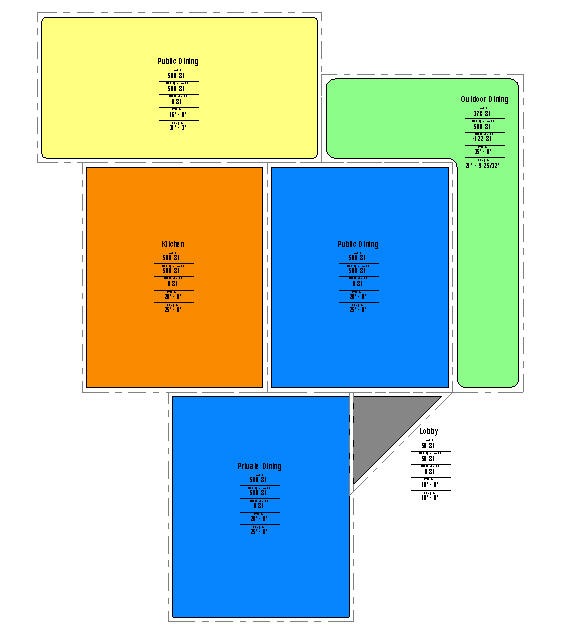
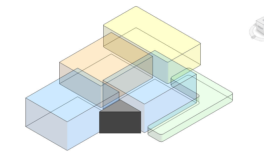
Spaces can be colored coded and display the same (or different) colors in 3D. Those colors can be solid or transparent (see images below) to best display your design concept.
Example of conceptual spaces in plan view:
Example in 3D view (with optional Transparency set on all except the Gray space):
While not shown in the image, even in 3D these objects can be tagged, manipulated and revised. The dashed lines (can be seen in plan view) are wall thicknesses which can be adjusted to show the proper spacing between entities. Standard commands such as Mirror, Copy, Array and Rotate work and do not effect the display of the tags (they will always read properly). Speaking of the Tags, they will always keep their relationship with their object as that object is moved around on screen, but the tag can be moved/adjusted independently with ease.
The best part is that these can be scheduled and a standard schedule with Circulation factor and more information is included. May it be by the department, by floor or however you want it to display, the schedule will provide the properties you need to get immediate feedback. In fact, you can even update the schedule with information such as “Program SF” and get back the difference you need between the Program SF and the Actual SF of the space you created on the screen. As a result, you will know immediately if you are meeting your program requirements. This information can/does show on the tag as well!
This is just the start of what can be accomplished using these tools. They can be customized to meet your workflow and when completed, can even become the basis by which the initial layout of the Revit model is created.
Get in touch with us if you are interested in the cost or would like a further demonstration.
Contact Brian Myers at [email protected] for technical questions or Harvey Wright at [email protected] to discuss pricing!
These tools will be available without cost for clients with a support contract with Seiler. Just contact us for information.


Leave A Comment