
Designing a pipe network can often involve either an existing or proposed roadway, or both. After design and modeling a Pipe Network and adding it to a Profile View in Civil 3D, it’s important to have labels that provide the information needed and to differentiate the different types of labels. Building a Profile View with a Pipe Network is also an option. The video below takes a quick look on how to add labels to entire pipe networks, Pipes and Parts into an existing profile view and how to choose Default Styles for the Pipe Network Labels in a few easy steps.
—
Like with most commands in Civil 3D, there are several ways to add labels to a pipe network, pipes, or structures. Below are a few of the ways to add labels to pipes and structures that are covered in the video above.
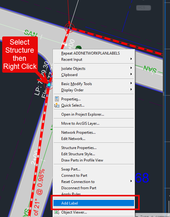
1. Selecting the pipe or Structure and Right Clicking
- Select Pipe or Structure
- Right Click
- Add Labels
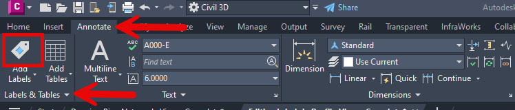
2. Through the Ribbon
- Go to the Annotate tab –> Labels & Tables panel –> Add Labels icon
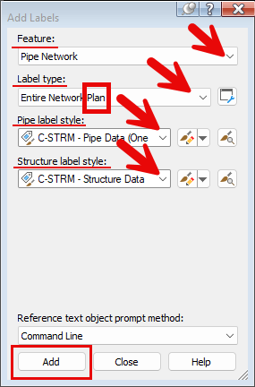
- Choose the Pipe Network Feature
- Choose Label type (note: if you’re selecting in Plan view, make sure the Label type is for Plan view)
- Choose the Pipe and Structure label styles
- Select Add
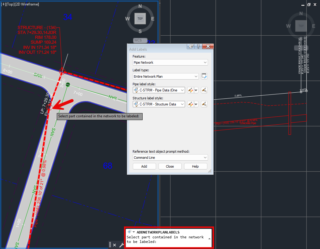
- Choose the Pipes and Structures to label
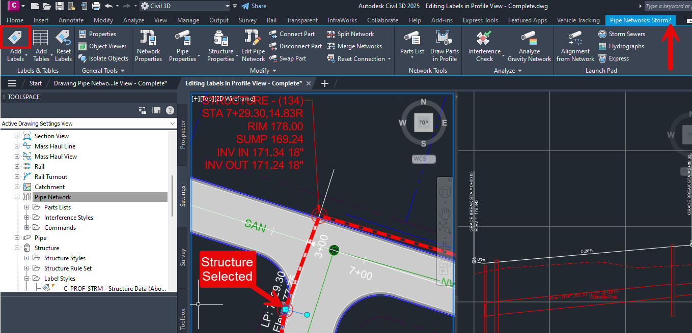
3. Using the Contextual Ribbon after selecting part of the Pipe Network
- Select the Pipe or Structure in the model
- Go to the Pipe Network contextual tab –> Labels & Tables panel –> Add Labels icon
- Follow the steps above for adding labels through the Add Labels icon
Check out these blogs for more how to’s leading up to adding labels to a Pipe Network:

Leave A Comment