If you are like most designers or engineers, you have probably worked on projects where cut and fill volumes were required on each cross section, and you were the lucky one chosen who had to sit and calculate all the volumes by hand. The problem is, when you finally finished doing the calculations, you found out the 3D model had changed, and it all needed to be redone, starting over again from the very beginning. Unfortunately, this usually happened multiple times over the length of the project. Not only did you have to recalculate the volumes, but you also had to update the volume callouts to match the new numbers.
If this has happened to you, and you are looking for a better solution, I can show you, in just a few easy steps, a way to have Civil 3D calculate the volumes, and insert a table on each section that shows the cut and fill volumes, which will then dynamically update whenever the 3D model is changed.
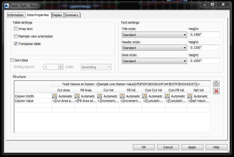
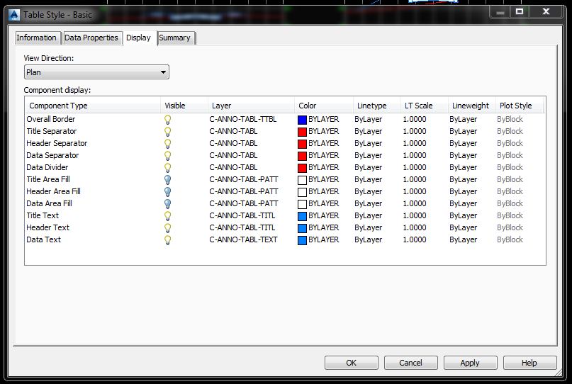
To accomplish this, the first thing that you want to do, is create a section view table, based on how you would like the volumes to show on your cross sections. This is done by opening the section view module under the settings tab on the toolspace. Open the node next to table styles, right click on total volume, and choose new. This will open a dialogue box, allowing you to custom create the table you would like to use for your sections. Under the information tab, give your style a name and description if you like. Change the tab to data properties. Here is where you can pick your text settings, sizes and which volumes you would like to use. Lastly, go to the display tab, and choose the layers for your new table. Click on apply and ok, and you are ready to go!
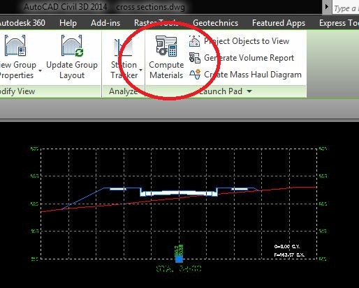
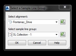
Once your section view table is complete, you may choose the compute material button 1 of 2 different ways, either by clicking on a section view and choose compute material in the launch pad in the ribbon, or switching to the analyze tab, and choose compute material in the volumes and materials panel. This will bring up a dialogue box that allows you to pick an alignment and sample line group from the drawing.
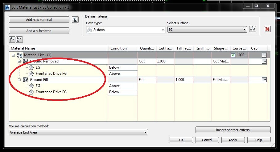
Once you choose your settings, click ok, and the compute materials list dialogue box opens. Next, pick your quantity takeoff criteria from the list, and the volume calculation method that you would like to use. Set the existing and proposed surfaces you would like in the section below. Once you have the settings completed, it is time for the next step.
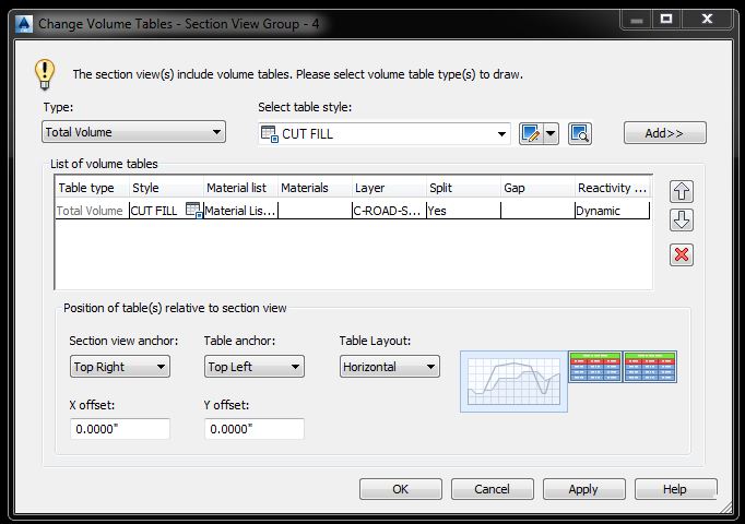
You are now ready to create your cross sections. When you choose create multiple section views, you will notice that section view tables is no longer grayed out. This is because we have already computed the materials list. When you get to this section, please choose total volume for the type of table, and your custom table for the style. Click the add button on the right. This area also lets you choose the position where you would like the table to be located based on the section view.
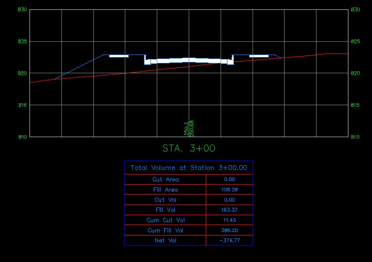
Click on create section views, and they will now have tables attached.
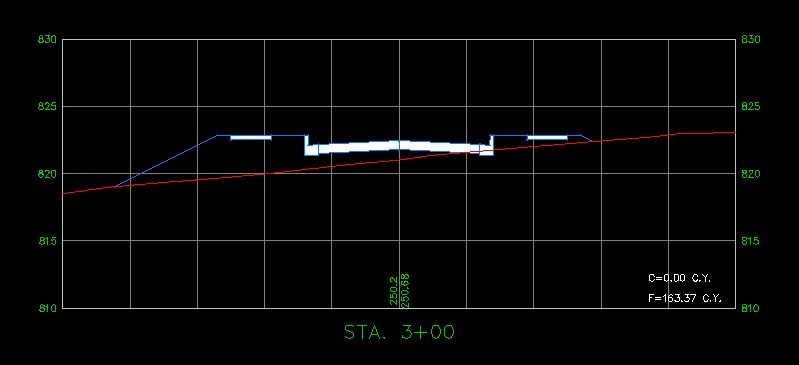
Below is another example of a volume table customized for your standards.
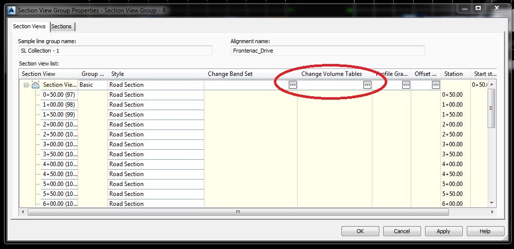
Don’t worry if you forget to add the table when creating the views. It is easy to add them later if needed. To accomplish this, highlight an existing section view. In the ribbon, click on view group properties, and under the section view tab, click on the change volume table ellipse (the small button that looks like a dice). Choose the table to add to the sections and hit ok. This will also allow you to change the location of the table on existing sections, if needed.
Just by accomplishing these few simple tasks, you will have cut and fill volumes located on each of your cross sections, that will dynamically update if the 3D model changes, and give you more time to devote to other projects.
Any questions, please reply to this blog, or contact me at [email protected].


Leave A Comment